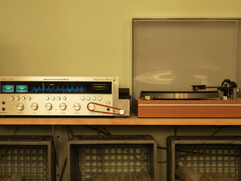
Arduino-powered remote volume control for my vintage stereo receiver
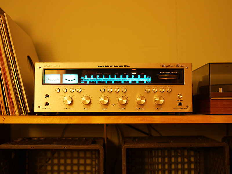
I've had this trusty Marantz 2270 for several years. I re-capped it when I got it and it
sounds fantastic. The only problem is that it also plays the sound while I watch movies, and
it's the only thing in my system that isn't remote-controllable. So I decided to change that.
I ordered the following items from Adafruit, very cool and highly recommended people:
Arduino Uno R3 (Atmega328 - assembled) - Main Arduino board
Adafruit Motor/Stepper/Servo Shield for Arduino v2 Kit - v2.3 - Motor control board
Small Reduction Stepper Motor - 5VDC 32-Step 1/16 Gearing - Stepper motor
Aluminum GT2 Timing Pulley - 6mm Belt - 20 Tooth - 5mm Bore - Pulley for motor
IR sensor - TSOP38238 - IR sensor to receive the remote signal
9 VDC 1000mA regulated switching power adapter
- Power supply
The total with shipping was around $75. There are cheaper alternatives to the Adafruit motor driver board
for driving a single motor, but since this was my first Arduino project I thought I'd keep things
as simple as possible.
First, in order to get used to working with the Arduino board, I downloaded the software and
ran the "blink" example, which makes the LED on the main board blink. Everything worked great
and was simple to set up, so I installed the motor driver board and got that working next.
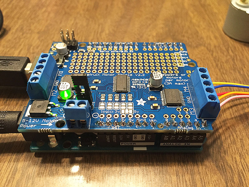
I started by soldering the header pins to the board and connecting up the motor. I used the on-board
9v (actually closer to 8) to drive the motor by using the included jumper. If I was running the
motor constantly that might be too much for my 5v rated motor, but for my short intermittent use it
shouldn't hurt:
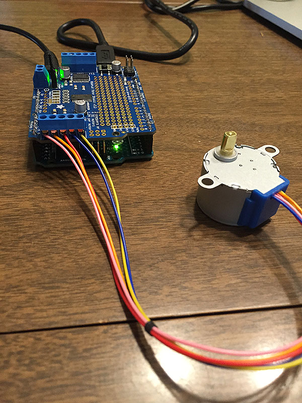
I then installed the Adafruit MotorShield library on my computer and tried uploading the stepper
motor test to make sure everything was working. Unfortunately, my motor wasn't moving at all. I
poured over the Adafruit forums to find tips, and I
eventually found somebody with the same
problem who had been using the old v1 version of the library, and that turned out to be my exact
problem. I installed the newer v2 library and the motor turned as it should!
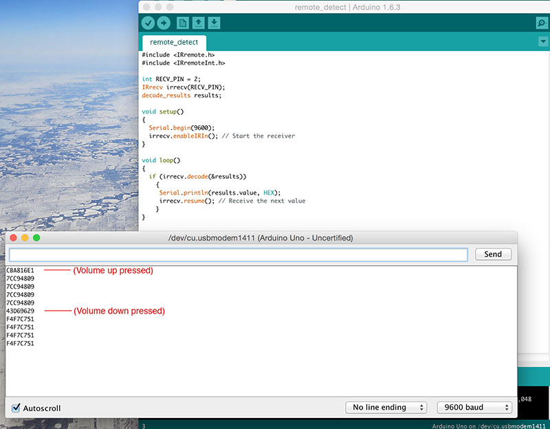
Next I temporarily soldered the IR receiver to the board so I could see how that worked.
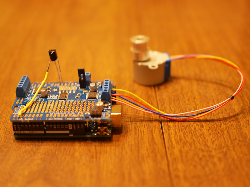
I found this handy tutorial that had great instructions and code for extracting the hex codes
my remote would be sending. I uploaded their code (reprinted here for ease) to the Arduino:
#include <IRremote.h>
#include <IRremoteInt.h>

int RECV_PIN = 2;
IRrecv irrecv(RECV_PIN);
decode_results results;

void setup()
{
  Serial.begin(9600);
  irrecv.enableIRIn(); // Start the receiver
}

void loop()
{
  if (irrecv.decode(&results))
    {
     Serial.println(results.value, HEX);
     irrecv.resume(); // Receive the next value
    }
}
When I ran this and looked at the serial output, I was able to see the hex values received
from my universal remote when I pressed the up/down volume buttons. You can see the values here:
All that was left to do code-wise was to combine the stepper motor code and the IR code to make the
motor turn in either direction when the remote button was pushed. I found this tutorial
that was doing almost exactly what I was, but using slightly different hardware. I borrowed some
of this code and combined it with some from the stepper motor test. Here's what I ended up with:
#include <Wire.h>
#include <Adafruit_MotorShield.h>
#include <IRremote.h>

// Create the motor shield object with the default I2C address
Adafruit_MotorShield AFMS = Adafruit_MotorShield();

// Connect stepper motor with 32 steps per revolution
// to motor port #1 (M1 and M2)
Adafruit_StepperMotor *myMotor = AFMS.getStepper(32, 1);

/*----- Variables, Pins -----*/
int receiver = 2; // Signal Pin of IR receiver to Arduino Digital Pin 2

/*-----( Declare objects )-----*/
// Setup of proper sequencing for Motor Driver Pins
// In1, In2, In3, In4 in the sequence 1-3-2-4

IRrecv irrecv(receiver);    // create instance of 'irrecv'
decode_results results;     // create instance of 'decode_results'

void setup()
{
  irrecv.enableIRIn(); // Start the receiver
  Serial.begin(9600);  // set up Serial library at 9600 bps
  AFMS.begin();  // create with the default frequency 1.6KHz
  myMotor->setSpeed(200);  // 200 rpm
}


//main loop to listen for remote IR signal and move motor

void loop()
{
  if (irrecv.decode(&results)) // have we received an IR signal?

  {
    switch (results.value)

    {

      case 0xCBA816E1: // UP button pressed
        myMotor->step(35, BACKWARD, SINGLE); //I need backward motion to turn my volume knob up
        //delay(200);  this was in the original code but I decided no delay was better
        myMotor->release(); //saves stepper from using voltage and getting hot at rest
        break;

      case 0x43D69629: // DOWN button pressed
        myMotor->step(35, FORWARD, SINGLE);
        //delay(200);
        myMotor->release();
        break;

    }

    irrecv.resume(); // receive the next value
  }


}/* --end main loop -- */
You'll notice there are some notes in the code. One important thing I learned is that stepper motors
stay energized and therefore get hot when sitting idle. I didn't want that since my motor would almost
always be idle; I found that the release() bit of code would de-energize it when not moving.
My hardware and code was now working as intended!
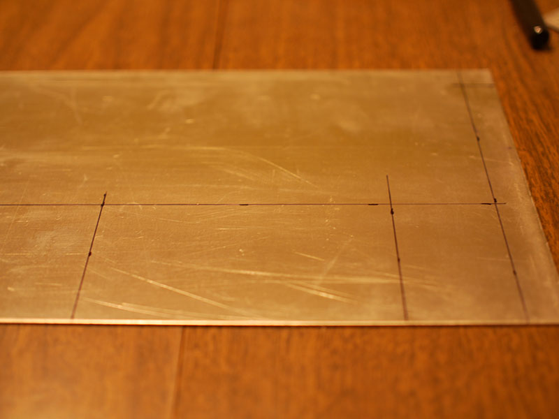
Next up I needed to make a bracket that could hold all this business together and attach it
to the receiver, while leaving the receiver intact so it's 100% removable. I had some .05" aluminum
from a previous project which seemed perfect for the job. First I drew out the lines to cut/bend:
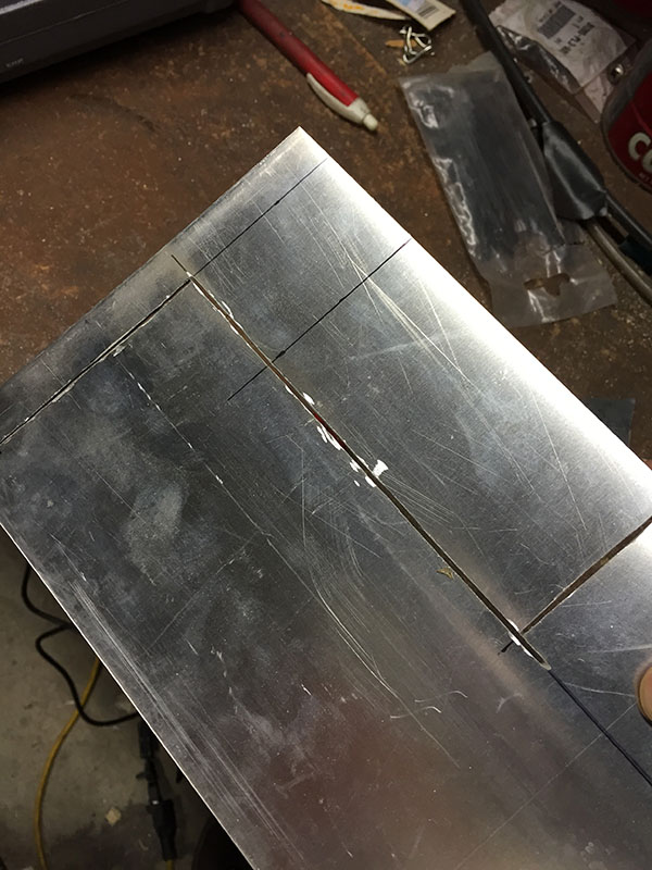
Out in the garage, I made use one of the useful tools in my arsenal: a Dremel with a cutoff wheel:
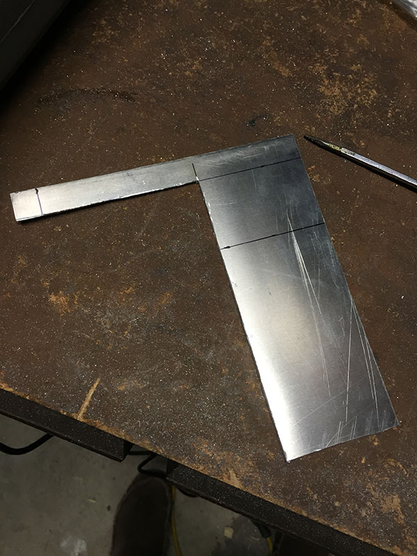
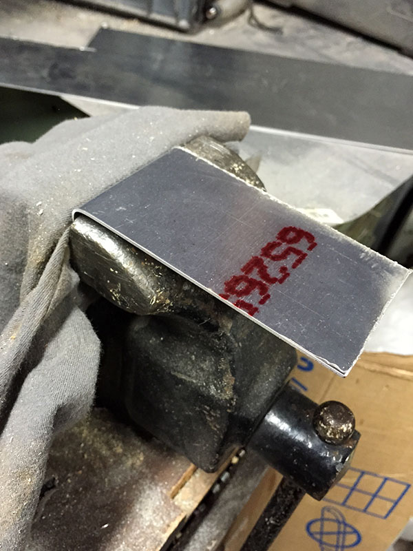
After filing the edges clean, I made the single right-angle bend in the vise:
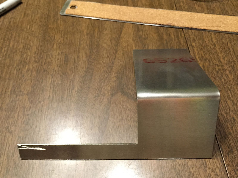
Here's what I had pre-drilling. I actually made a measuring mistake, so I ended up re-making
the bracket, and like a cooking show, this is not the one I ended up using.
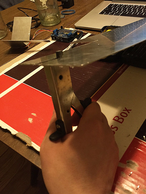
For the second one I decided to use my "nibbler," a tool which has a funny name
and is very useful
for cutting straightish lines in sheet metal.
Ollie waited (somewhat) patiently for me to do all this work.

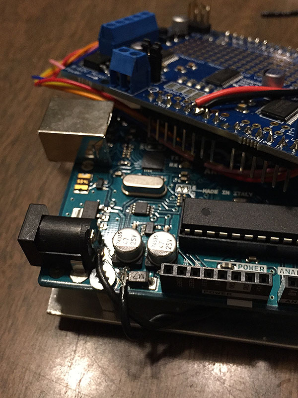
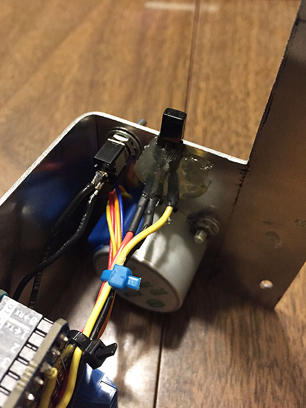
I decided I didn't want the Arduino to be powered on all the time using up energy,
so in order to
install a power switch I cut one of the traces from the power jack and
soldered a toggle switch in between.
Here you can see the toggle and the IR receiver, which I used hot glue to affix
to the back side of the bracket, just protruding to catch the signals.
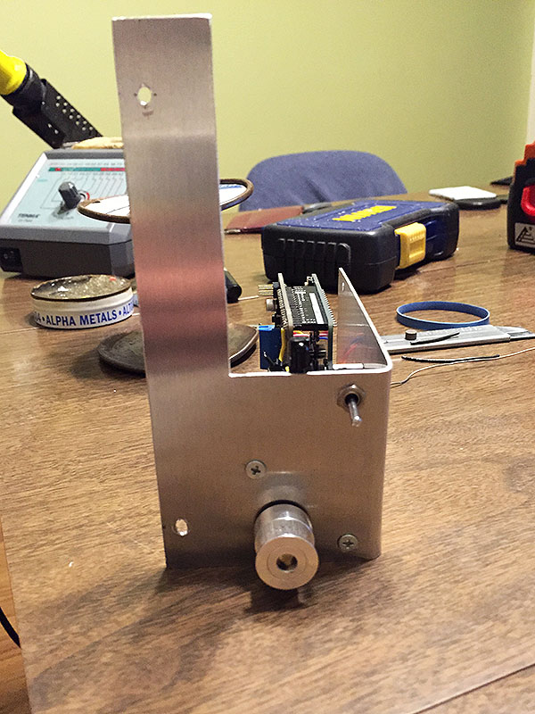
The completed unit, assembled and ready to install!
I hadn't really thought ahead about a drive belt, and had figured a standard rubber band would work ok.
I didn't consider all the stretching the band would do though, so when the volume changed directions
it would take several steps of movement to get the volume knob moving. I ended up deciding o-rings
would probably do the trick nicely.
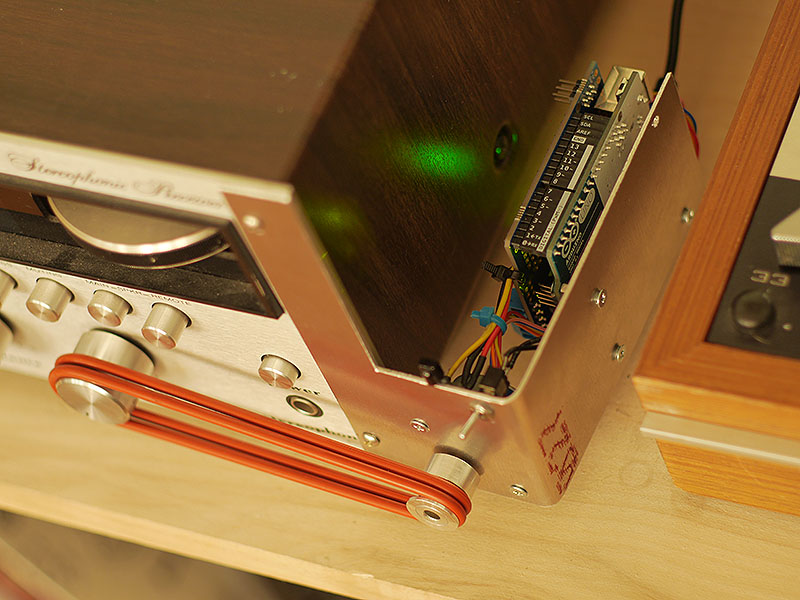
I used string to measure around both pulleys and ordered a few different sizes of o-rings around
that circumference. One of them fit very well, without exerting too much force on the volume pot,
and I doubled it up to get more friction.
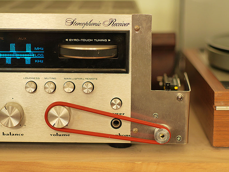
The bracket is in place and the unit works great! I fiddled with the number of steps the motor used in order
to get a good amount of granularity while also not taking forever to turn the knob a good distance.
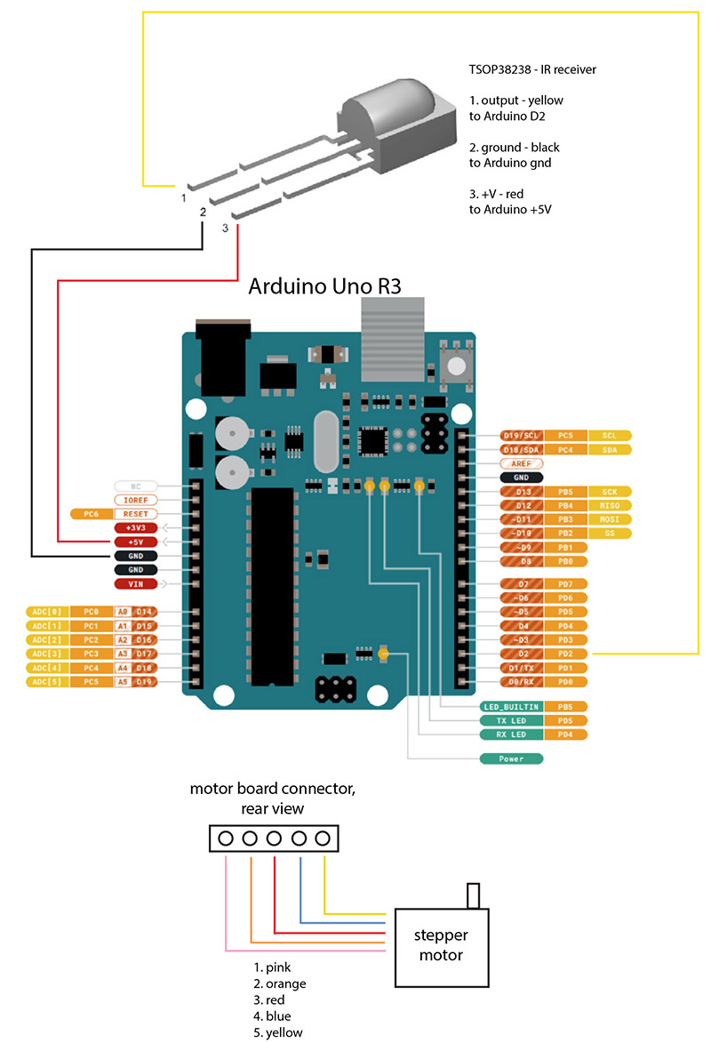
A user asked me for a wiring diagram so I made a quick one here:
Here's a video of the volume control in action:
If you can't see the video please click here
Thanks for reading! If you have any questions feel free to contact me at: